writing a new release packed with new and useful features which will even further establish Revit Platform as the tool of choice for more design professionals. But what if you were an old-fashioned believer in the open source or (almost open source) application that has the potential and the technology to be the BIM platform of choice for those that are not willing to go with an OOTB product, and for those that believe that the power of information lies in its ability to be interpreted and cross-referenced in a way that suits the uniqueness of your way of doing business. So for those of you that still like to use ADT 2006 or for those that feel a little bit more adventurous and are using 2007, here is a workaround that I have cooked up in order to link partition height to Project Level Height and to the Slab thickness associated to that level. I know Revit does this in quite an elegant way, but there is really no reason why ADT should not do it, and do it even better by being able to customize the relationship between AEC entities and ADT project parameters.
To accomplish this I wrote a relatively simple VBA code based on the examples that are part of the Active X help file, created a Property Definition Set in conjunction with a Display Theme that allows me to quickly identify those walls that will follow the dependency rule.
The first and the easiest part was to define a custom Project property and I have labeled it Slab Thickness with a given default value.
Start a new project (or open an existing one), and within the Project Navigator under the Project Tab proceed to Project Edit -> Edit Project Details. For project details add a new category Structural Info (fig.01), and within this category make a new entry for Slab Thickness (fig.02) and assign it a value of 12.
|
|
| fig.01 | fig.02 |


This step has created a new project variable that can be invoked during the wall height adjustment calculation within the Wall Object based Property Definition Set. To have this set function properly our ADT project should have levels defined in order to locate the new partition constructs.
|
| fig.03 |

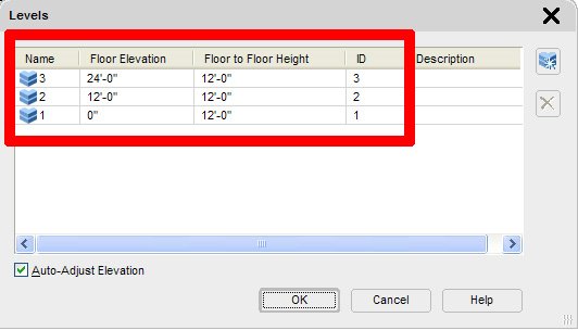
For the sake of this exercise the set of three levels (fig.04) has been determined within the project and by doing so we are setting up conditions where Level Height information will be used to determine the height of bound or attached ADT walls.
|
| fig.04 |
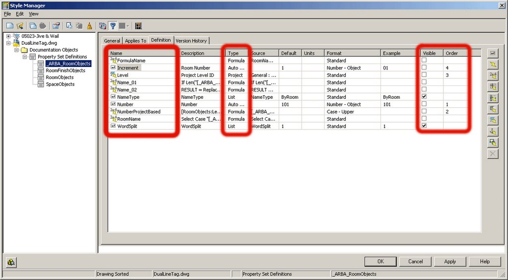
After these project parameters are defined and their values have been assigned, the Wall Object based Property Set Definition with the following Properties needs to be created and assigned to walls whose height property will become bound to the project values. For lack of better ideas I have named this new Property Set Definition as IWall (fig.03) and made it apply just to Wall objects. It is worth mentioning that this technique could be applied to any object or style if desired to do so, with a number of project based values that that will be reused throughout a project.
|
| fig.05 |
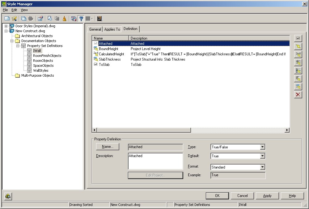
The first property in this set is a Manual Property Definition named Attached (fig.05) of a Boolean type, and it will be responsible for determining which walls will be associated with the project constraints.
|
|
| fig.06 | fig.07 |
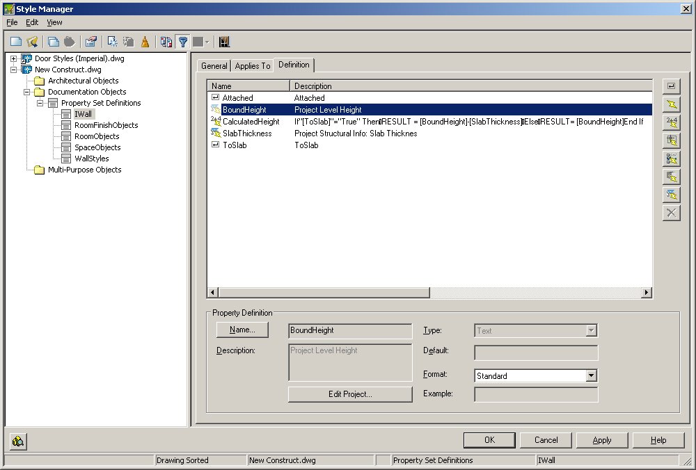
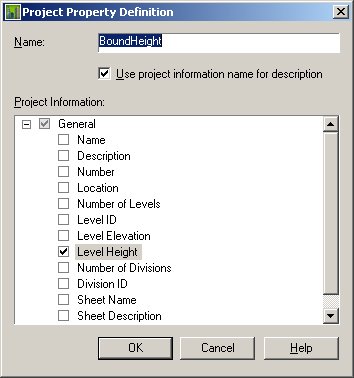
The second property that will play a role in determining attached walls’ height is named BoundHeight (fig.06) and its value is retrieved from Project Property Definition set as a Level Height (fig.07) property. We thereby effectively establish the relation between the wall entity and project properties.
Now in order to give some flexibility to the entire system and to show how by, adding a few other variables, this can indeed become a useful “Parametric” tool, we will add two additional properties that will govern the outcome of our Formula Based calculated Property Definition.
|
|
| fig.08 | fig.09 |

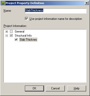
Slab Thickness, (fig.08) has been added as a project based property (fig.09), and I have to point out that with just a little bit more creativity and effort this property can be either allocated to individual levels or it can be retrieved from an entity within the model by writing some additional VBA
code.
|
| fig.10 |

 |
|
| fig.11 | fig.12 |

To be able to specify whether the wall is connected to the underside of the slab ToSlab (fig.10) Manual Property Definition in Boolean (True False) format, has been introduced so that user can specify which walls in the model adheres to these rules.
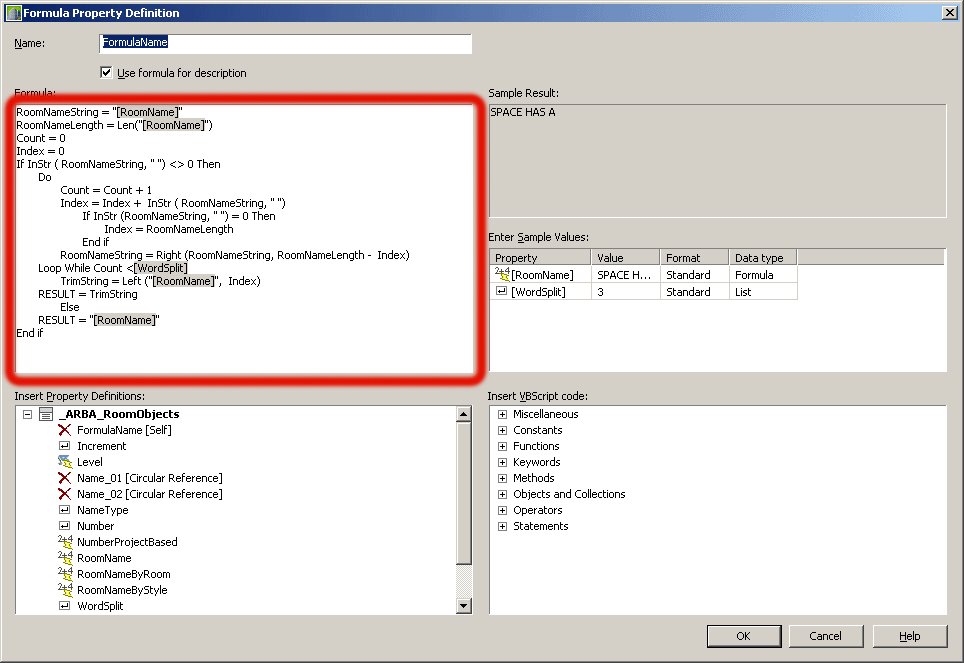
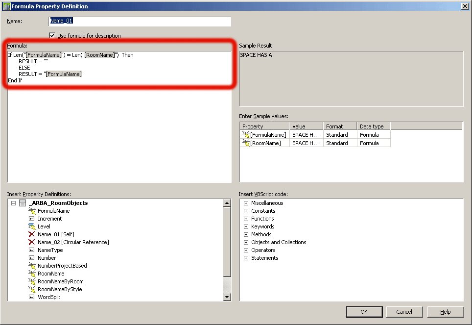
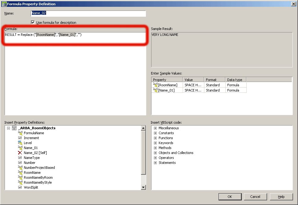
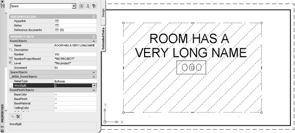
When all of the above properties have been assigned, the Formula Based Property CalculatedHeight (fig.11)(fig.12) will provide for the modification of AecWall BaseHeight property.
This puts us only half way through this exercise and the true engine that drives this is actually placed within these relatively simple lines of VBA code that is mostly based on the examples that came with ADT installation.
To make this work, copy the code below into a new module. From this point on when an event fires it will call this ParaWall Sub which parses the database in search of linked AecWalls and adjusts their height to the one that is associated with the current level where the construct resides. The value is pulled from the Property Set Definition, more precisely, from CalculatedHeight Property Definition and assigned to the AecWall object.
To have this working make sure that it loads with every new document so under the ADT help file look for the following topic: ”Automatically Load and Execute VBA Projects”, and make sure that your VBA project has the following code placed respectively under the “This Drawing” section and in a Module of your choice. In order to simplify the coding and use I decided to call the routine only in two instances; when loading a construct or when the REGEN command has been invoked.
Private Sub AcadDocument_Activate()
 ParaWall
End Sub
Private Sub AcadDocument_EndCommand(ByVal CommandName As String)
 If CommandName = "REGEN" Or CommandName = "REGENALL" Then
    ParaWall
 End If
End Sub
Sub ParaWall()
 Dim doc As AecArchBaseDocument
    Dim wallObject As AecWall
    Dim Object As AcadObject

    Dim SchedApp As New AecScheduleApplication
    Dim cPropSets As AecSchedulePropertySets
    Dim PropSet As AecSchedulePropertySet

    Dim cProps As AecScheduleProperties
    Dim prop As AecScheduleProperty

    Dim count As Integer
    Set doc = AecArchBaseApplication.ActiveDocument

    For Each Object In doc.ModelSpace

        If TypeOf Object Is AecWall Then
            Set wallObject = Object
            Set cPropSets = SchedApp.PropertySets(wallObject)

            If (cPropSets.count > 0) Then
            Set PropSet = cPropSets.Item("IWall")
            Set cProps = PropSet.Properties
                    If cProps.Item("Attached").Value = True Then
                        Set prop = cProps.Item("CalculatedHeight")
                        wallObject.BaseHeight = prop.Value
                    End If
            End If
        End If
    Next

End Sub
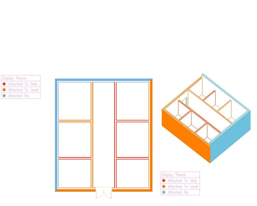
To make all of this just a little bit more effective, I have also created an Display Theme that will allow me to quickly identify those walls in the construct that are bound either to the Level Height or to the adjusted height that takes into account the size of the structure.
This is just a very brief example of what can be accomplished in not only automating ADT, but customizing its database in order to provide for user definable parametric relationships within the project.
For those of us that think that implementing BIM methodology is not about which software tool we use but about how effectively this tool facilitates our need for extracting usable project information, much more can be accomplished if bending the rules becomes the modus operandi.
|
If you think that this example is of any use, feel free to download this sample file and test it on one of your projects.
Until next time….